RE60-JFN
RADIAFLEX® Elliptical Waveguide, RE-series
Rev : D | Rev date : 15 Nov 2025
- RADIAFLEX® series functions as a distributed antenna to provide communications in tunnels, mines and large building complexes and is the solution for any application in confined areas.
- Slots in the copper outer conductor allow a controlled portion of the internal RF energy to be radiated into the surrounding environment. Conversely, a signal transmitted near the cable will couple into the slots and be carried along the cable length.
- RADIAFLEX® is used for both one-way and two-way communication systems and because of its broadband capability, a single radiating waveguide can handle multiple communication systems simultaneously.
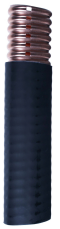
- This RADIAFLEX® radiating waveguide is constructed of longitudinally continuous seam welded, highly conductive copper tube, corrugated and precision formed into an elliptical cross section. It is manufactured in continuous lengths using a special seam welding process developed by the RFS organization. The product offers a superior electrical performance together with good bending properties.
Feature / Benefits
- Optimized for ultra high frequency applications from 4.9 GHz to 6.0 GHz
- Best-in-class, RF wideband radiating waveguide with technology agnostic performance
- Designed for a variety of in-tunnel applications
- Lowest insertion loss and excellent coupling performance to minimize count of active equipment; low coupling loss variations
- Maintains functionality even in case of a fire
Technical features
General Specifications
|
Electrical Specifications
|
||
|
||
|
Mechanical Specifications
|
||
|
||
|
||
|
||
|
||
|
||
|
||
|
||
|
||
|
||
|
Testing and Environmental
|
Temperature Specifications
|
||
|
||
|
Attenuation and Power Rating
|
|
|
- Coupling loss as well as longitudinal attenuation of RADIAFLEX® elliptical waveguides is measured by the free space method according to IEC 61196-4.
- Coupling loss values are measured with a log-periodic antenna with gain of approx. 6 dBi in specified frequency range.
- The coupling loss values are average values of the three spatial orientations (radial, parallel and orthogonal) of log-periodic antenna.
- Coupling loss values are given with a tolerance of ±6 dB and longitudinal loss values with a tolerance of ±5%.
- As with any radiating element, the performance in building or tunnel enviorments may deviate from figures based on free space mthod.