- Home
- Cables & Waveguides
- RADIAFLEX Radiating Cables
- 1/2"
- RCF12-50JFN
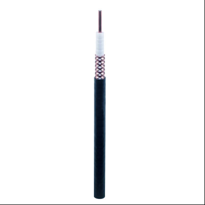
RCF12-50JFN
1/2" RADIAFLEX® RCF Cable
Rev : B | Rev date : 15 Nov 2025
- RADIAFLEX® functions as a distributed antenna to provide communications in tunnels, mines and large building complexes and is the solution for any application in confined areas.
- Slots in the copper outer conductor allow a controlled portion of the internal RF energy to be radiated into the surrounding environment. Conversely, a signal transmitted near the cable will couple into the slots and be carried along the cable length.
- RADIAFLEX® is used for both one-way and two-way communication systems and because of its broadband capability, a single radiating cable can handle multiple communication systems simultaneously.
- This RADIAFLEX® radiating cable utilize a low-loss cellular polyethylene foam dielectric and a corrugated copper outer conductor which offers a combination of remarkable flexibility, high strength and excellent electrical performance.
Feature / Benefits
- Broadband radiating cable supporting all wireless application between 75 MHz to 6000 MHz
- Ideally suited for application that require low bending radii
- Robust radiating cable operational under all enviromental conditions as e.g. harsh tunnels or mines
Technical features
General Specifications
|
Electrical Specifications
|
||
|
||
|
||
|
||
|
||
|
||
|
||
|
||
|
||
|
Mechanical Specifications
|
||
|
||
|
||
|
||
|
||
|
||
|
||
|
||
|
||
|
||
|
||
|
||
|
||
|
Testing and Environmental
|
Temperature Specifications
|
||
|
||
|
Attenuation and Power Rating
|
|
|
- Coupling loss as well as longitudinal attenuation of RADIAFLEX® cables are measured by the free space method according to IEC 61196-4.
- Coupling loss values are average values of all three spatial orientations (radial, parallel and orthogonal) of dipole antenna.
- Coupling loss values are given with a tolerance of +10 dB and longitudinal loss values with a tolerance of +5%. Note: Measured values below nominal are better. They are not limited by any tolerance-range.
- As with any radiating cable, the performance in building or tunnel environments may deviate from figures based on free space method.